Solar PV Mounting Fasteners: Mid Clamps, End Clamps, Rail Bolts and Grounding Lugs for Rooftop and Ground-Mount Systems
A solar array looks like a field of glass and aluminium held down by clips. The clips are the product most often bought as an afterthought. On a rooftop in a coastal town, a mid clamp that was not torqued to the module manufacturer's specification works loose in the first winter wind, the module lifts at the corner, the glass edge contacts the rail, and two years of microcracks later the string is underperforming. On a ground-mount farm in the desert, a carbon-steel rail bolt that was zinc-plated instead of Zn-Al-Mg shows red rust at the head after one wet season, and the EPC has to send a crew out on a scissor lift to replace hardware that should have lasted twenty-five years.
The mounting hardware is what transfers wind uplift, snow load and module weight from the glass frame into the aluminium rail, from the rail into the roof hook or the ground-mount post, and into the roof structure or the concrete foundation. It is also the bonding path that grounds the array for lightning and fault protection. Getting the clamp type, the stainless grade and the coating right at procurement is cheaper than sending a lift truck out across a 50 MW site.
WF Fastener manufactures solar PV mounting fasteners — mid clamps, end clamps, rail-splice bolts, roof-hook screws, channel nuts and grounding lugs — for solar module mounting structure (MMS) suppliers, EPC contractors and PV developers across Europe, the Middle East, Southeast Asia and Australia. Our production follows ISO and EN systems: ISO 3506 for stainless-steel fastener mechanical properties (A2-70, A4-70, A4-80), EN 10088 for the underlying stainless material grades (1.4301 / 304, 1.4404 / 316L), and EN 14566 where the building or construction fastener scope calls it up. This guide covers where each mounting hardware position sits, how the material and coating choices split between rooftop and ground mount, and what an RFQ should carry so the delivered clamps and bolts match the rail profile and the module frame on day one.
For the broader renewable fastener range, start at the renewable energy fastener manufacturing center.
WF Solar Mounting Fasteners — Quick Reference
- Module clamps: mid clamps (between modules) and end clamps (outer edge), extruded aluminium body with stainless bolt
- Rail hardware: T-bolts / hammer-head bolts for slotted rails, rail-splice bolts, channel nuts
- Roof interface: roof-hook screws, lag bolts, EPDM-sealed penetration bolts
- Bonding: grounding lugs, toothed washers, rail-to-earth bonding straps
- Stainless grades: A2-70 (1.4301 / 304) for inland; A4-70 / A4-80 (1.4404 / 316L) for coastal, salt, aggressive
- Structural coatings: Zn-Al-Mg (zinc-aluminium-magnesium) or zinc flake per ISO 10683 on steel rails and posts
- Sizes: M6 to M12 most common; M16 on large ground-mount post connections
- Documentation: EN 10204 3.1 for stainless lots; coating thickness and salt-spray records
1. The Mounting Hierarchy: Where the Fasteners Sit
Before choosing a bolt, know which joint it goes into. A PV array transfers load through a chain, and each link has a different hardware requirement:
| Joint | Hardware | Typical material | Load logic |
|---|---|---|---|
| Module frame to rail | Mid clamp + end clamp, stainless bolt | Al clamp body + A2-70 / A4-70 bolt | Clamps the aluminium module frame edge |
| Rail to rail (splice) | Rail-splice bolt, T-bolt | A2-70 stainless or Zn-Al-Mg steel | Longitudinal continuity |
| Rail to roof hook / bracket | Hammer-head bolt, channel nut | A2-70 / A4-70 stainless | Wind uplift transfer to roof structure |
| Roof hook to rafter | Lag bolt / wood screw | HDG or stainless, structural | Penetration into roof structure |
| Ground-mount post to rail | Carriage bolt / hex bolt | Zn-Al-Mg or zinc-flake 8.8 | Wind and snow load to foundation |
| Array bonding to earth | Grounding lug, toothed washer | A2-70 / A4-70 stainless | Lightning and fault current path |
| Module frame bonding (where required) | Bonding jumper, lug | Stainless | Continuous equipment grounding conductor |
The two positions that drive the most custom orders are the module clamps (because every module frame height and every rail slot pattern is different) and the roof-hook screws (because the roof pitch, tile profile and rafter spacing change every project). The rest of the hardware is largely off-the-shelf once the rail profile is known.
2. Mid Clamps and End Clamps: The Module-to-Rail Joint
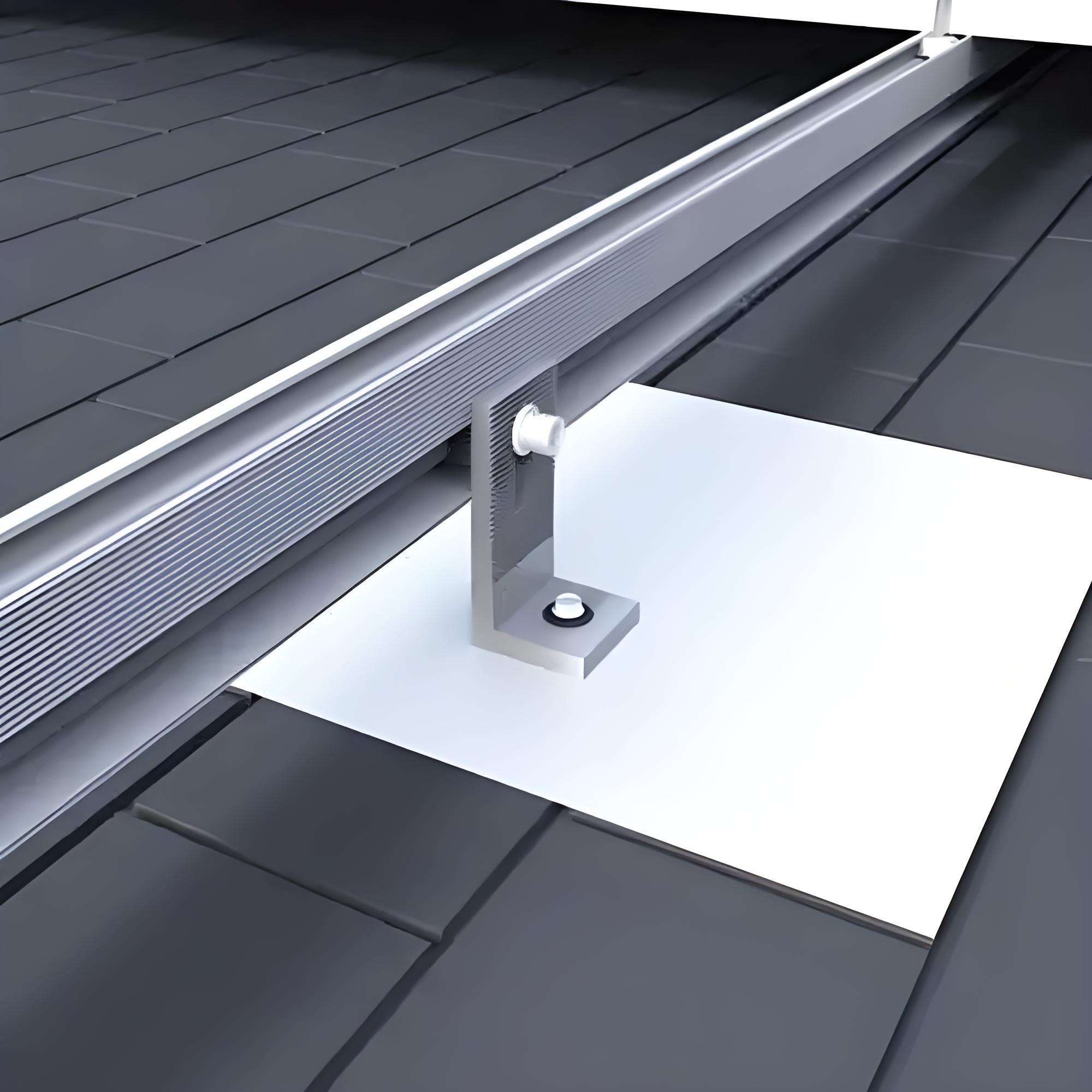
The clamp is the component that grips the edge of the module's aluminium frame and pulls it down onto the rail. Two forms:
- Mid clamp. Sits between two adjacent modules, gripping both frames from one body. It is the most numerous clamp on the array — typically two per module, one on each rail.
- End clamp. Sits at the outer edge of the module row, gripping the outer frame on one side. It has one clamping face and a back profile that matches the rail.
The clamp body is almost always anodised aluminium (6000 series), and the bolt that tightens the clamp to the rail is the stainless part. The critical dimensions:
- Clamp height. Has to match the module frame thickness, which varies by module manufacturer and by framed vs thin-film. A clamp that is too tall leaves the bolt doing the work instead of the clamp body; one that is too short does not contact the frame. State the module model or the frame height on the RFQ.
- Rail slot engagement. The T-bolt or hammer-head bolt has to match the rail slot width (commonly 28 mm, 33 mm, 40 mm, or the slotted aluminium profile used by the MMS supplier).
- Torque. The clamp bolt is torqued to the module or MMS manufacturer's specification — commonly 12–20 Nm on M8 stainless. Under-torque and the module lifts in wind; over-torque and the clamp cracks the frame edge. The friction condition of the stainless bolt matters here: the stated Nm value is built around a documented friction coefficient μ (nut factor K), and dry stainless runs high and variable, which is why anti-seize and the MMS torque table are applied together rather than torquing dry to a guessed value.
The field failure pattern: a mid clamp bought to a generic height on a site using a new thicker-frame module, so the clamp bottoms out on the rail before it grips the frame. The module moves in the first wind event. Order clamps to the module frame height, not to a catalog size.
3. Rail Hardware: T-Bolts, Hammer-Head Bolts and Splice Joints
Aluminium rails come with a slot along the length, and the fasteners that drop into that slot are a family of their own:
- T-bolt / hammer-head bolt. A bolt with a flattened head that drops into the rail slot, rotates a quarter-turn, and seats against the slot edge. Used to attach clamps, brackets and accessories to the rail. The head geometry is specific to the slot profile.
- Channel nut / spring nut. A nut that sits inside the rail slot, held by a spring, that a bolt threads into from outside. Used where a bolt passes through a bracket into the rail.
- Rail-splice bolt. Joins two rail sections end-to-end. The splice plate sits inside or on top of the rail, and the bolts transfer longitudinal load and maintain electrical continuity.
The material choice on rail hardware is driven by environment:
- Inland, non-coastal rooftop and ground-mount. A2-70 (1.4301 / 304) stainless is the default. It is corrosion-resistant for a C3 atmosphere and costs less than A4.
- Coastal, salt-spray, agricultural or industrial. A4-70 / A4-80 (1.4404 / 316L) stainless. The molybdenum in 316L resists chloride pitting that 304 will not.
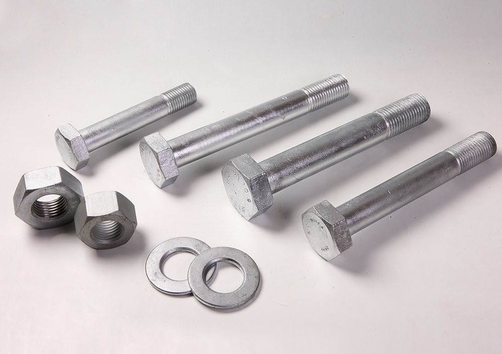
- Ground-mount steel posts and heavy rail splices. Zn-Al-Mg coated structural steel, or zinc-flake per ISO 10683, where the load is higher and the bolt is carbon steel rather than stainless.
We cover the coating side in detail in our zinc-flake coated bolt guide to ISO 10683. The solar addition is that the stainless clamp bolts and the coated structural bolts often live on the same array, and they are specified on separate line items.
4. Roof Interface: Hooks, Lag Bolts and Penetrations
On a rooftop array, the hardware that goes through the roof membrane is the most failure-prone position, because a leak here costs the customer the ceiling below the array.
- Roof hook. A stainless or aluminium bracket that clips under the tile or slate and bolts to the rafter. The hook itself is part of the MMS, but the screws that fix it to the rafter are the fastener: a lag bolt or structural wood screw, sized by the rafter species and the uplift load from the array.
- Penetration bolts. On flat-roof ballasted systems and some commercial rooftop systems, a bolt may penetrate the membrane or the standing-seam seam. These are always sealed — EPDM washer, neoprene gasket, or a pre-formed flashing — and the bolt material is stainless or HDG, never bright zinc-plated, which will corrode at the seal.
- Ballast tray hardware. On flat-roof ballasted systems, the tray and the rail are clamped together with stainless T-bolts and channel nuts; no roof penetration at all.
The practical rule for rooftop buyers: specify A2-70 or A4-70 stainless on every bolt that touches the roof penetration, and state the roof type (tile, slate, metal standing-seam, flat membrane) on the RFQ. The roof-hook screw size and the seal kit change with the roof type.
5. Grounding and Bonding Lugs
A solar array is a metal framework on top of a building or in an open field, and it has to be electrically continuous for both lightning protection and equipment grounding. The bonding hardware is not optional:
- Grounding lug. A lug, often with a serrated or toothed washer, that bites through the anodised rail coating to make an electrical contact. It bonds the rail to the equipment grounding conductor.
- Toothed / bonding washer. A star washer or serrated washer that cuts through anodised aluminium and paint to provide a low-resistance contact under the bolt head.
- Bonding jumper. A braided or stranded copper jumper with stainless lugs, where a sliding rail joint or a tilt-table joint would otherwise break the bonding path.
The material on bonding lugs is stainless A2-70 or A4-70, and the lug is sized to the bonding conductor (commonly 6 mm² to 16 mm² copper). The field mistake: relying on the clamp bolt itself to provide the bonding path, when the anodised rail and the painted module frame insulate the joint. The bonding lug is a separate, specified line item selected to the project earthing design and the local electrical code — not chosen off the hardware shelf. The same toothed/serrated contact principle carries over to the cabinet and rack earthing hardware we detail in our BESS rack and battery cabinet fasteners guide.
The bonding and lightning design itself is governed by the project's earthing and lightning-protection design (referenced to IEC 62305 and the local electrical code); we supply the hardware that implements it, not the design.
6. Material Selection: A2-70 vs A4-70 vs A4-80
Stainless fasteners on a PV array are specified to ISO 3506, which gives the property class; for North American-specified projects the equivalent stainless bolt standard is ASTM F593, whose alloy-and-condition designations map onto these ISO 3506 classes.
| Class | Material (EN 10088) | Common name | Min tensile | Where it goes |
|---|---|---|---|---|
| A2-70 | 1.4301 (304) | 18/8 stainless | 700 MPa | Inland rooftop, non-coastal, C3 atmosphere |
| A4-70 | 1.4401 / 1.4404 (316 / 316L) | 316 stainless | 700 MPa | Coastal, salt-spray, C4 / C5 atmosphere |
| A4-80 | 1.4404 (316L), work-hardened | 316 high-strength | 800 MPa | Higher-load clamps, coastal where strength matters |
The engineering boundary: the "1–2 km from the coast" figure is a rule of thumb for starting the grade conversation, not a hard cutoff. Distance from the shore alone does not set the corrosion class — prevailing wind direction, onshore salt drift, humidity and dew, shelter, and agricultural or industrial deposition all move the site up the ISO 12944 ladder. Chloride-laden air pits 304 stainless within a few years once a C4 condition is reached, and a pitted clamp bolt cannot be removed for module replacement. The site corrosivity class (ISO 12944 C3, C4 or C5) is set by the project from these local factors rather than from a fixed shoreline distance; A4-70 / A4-80 follows for C4 and above.
A note on galling: stainless fasteners gall under torque, particularly A4-70 and A4-80. On clamp bolts torqued on site, anti-seize or a stainless-specific lubricant is applied per the MMS manufacturer's procedure, and the torque table is built for that friction condition. Dry torquing a stainless M8 bolt to a guessed Nm value is how crews snap clamp bolts. For the coastal and splash-zone side of the stainless grade choice, we cover the A4-80 / 316L selection in detail in our 316L offshore and coastal solar fasteners guide.
7. Coatings on Structural Steel Hardware
Where the hardware is carbon steel rather than stainless — ground-mount posts, heavy rail splices, large foundation bolts — the coating is the corrosion control:
| Coating | Standard | Typical use on PV structures | Notes |
|---|---|---|---|
| Zn-Al-Mg (zinc-aluminium-magnesium) | Per coil / coating spec | Ground-mount posts, purlins, heavy splices | Superior to HDG in cut-edge corrosion; thin |
| Zinc flake (Geomet / Delta type) | ISO 10683 | 8.8 structural bolts on ground-mount | Low hydrogen, controlled friction, thin film |
| Hot-dip galvanizing | ISO 10684 | External steel brackets, foundations | Thicker; threads over-tapped after galvanizing |
| Electroplated zinc | ISO 4042 | Avoid on external PV hardware | White rust and hydrogen risk on higher-strength |
The rule: do not electroplate solar mounting bolts for external use. Bright zinc-plated hardware rusts at the head within one wet season in a coastal or agricultural environment, and it is the most common substitution we see on budget PV packages. Zn-Al-Mg or zinc flake on the structural steel, stainless on the clamps.
8. Wind Uplift, Snow Load and the Torque Question
A PV array in a storm sees uplift, not downward load. The clamps and rail bolts have to hold the modules down against the wind trying to lift them off the roof. Two design points:
- Clamp torque. Set by the module and MMS manufacturer, commonly 12–20 Nm on M8. The installer torque wrench has to be calibrated and the friction condition (dry, lubricated) stated.
- Number of clamps per module. Set by the structural engineer based on wind load, module size and roof height. More clamps per module on a tall commercial rooftop than on a low residential roof.
- Snow load. In alpine and northern European sites, the downward snow load adds to the clamp compression; the rail splice and post bolts are sized for the combined load case.
We do not design the structural load path — that is the MMS supplier's or the project structural engineer's job, under IEC 62548 (design requirements for solar PV systems) and, for North American installations, ASCE 7 wind loads and the IBC / local building code. What we supply is the hardware that meets the clamp count, bolt size and torque specification the design calls for, with the material and coating matched to the site corrosivity.
9. Documentation for PV Project QA
A solar mounting hardware order on a utility-scale or commercial project is inspected like any other engineered fastener pack:
- EN 10204 3.1 material certificate for stainless lots, with chemistry confirming 1.4301 / 1.4404 per EN 10088
- Mechanical properties report: tensile and hardness within the A2-70 / A4-70 / A4-80 band per ISO 3506
- Dimensional report: clamp height, T-bolt head geometry, thread gauge fit
- Coating report where coated: Zn-Al-Mg or zinc-flake thickness, adhesion, salt-spray hours
- Lot traceability: heat number matching mill certificate to box label
- Clamp-bolt torque reference sheet, matching the MMS manufacturer's procedure
For project-witnessed lots — SGS, BV, TÜV, or the owner's QA — we hold the lot for witness testing before shipment. The heat number on the box label is what lets the EPC inspector tie the clamps on a specific rooftop array back to the certificate during the project close-out.
For the offshore and coastal wind side of our renewable range, where the corrosion environment moves from C5 atmospheric to splash-zone exposure, see the offshore wind bolted connections guide. The corrosion-control logic is the same; the splash-zone coating system is a step beyond what a coastal PV array needs.
WF Solar Mounting Manufacturing Capability
- Clamp range: mid clamps and end clamps for module frame heights from 30 mm to 50 mm, to rail slot patterns 28 / 33 / 40 mm and custom
- Stainless fastener range: M6 to M12 in A2-70, A4-70 and A4-80 to ISO 3506
- Structural bolt range: M10 to M16 in 8.8 zinc-flake and Zn-Al-Mg for ground-mount
- Testing: tensile tester, hardness tester, thread gauges (GO / NO-GO), coating thickness gauge, salt-spray chamber
- Monthly solar mounting output: on the order of 150–250 tonnes of clamp and rail hardware per month across rooftop and ground-mount, as combined production capacity depending on product mix
10. Supplier Evaluation Card
Use this card when comparing solar PV mounting fastener suppliers. The points below reflect what MMS manufacturers and EPC procurement teams ask for on qualification.
| Evaluation point | What to ask the supplier | Why it matters |
|---|---|---|
| Clamp range | Can they supply mid and end clamps to your module frame height and rail slot? | Generic clamps do not match the frame or slot |
| Stainless grade discipline | Do they ship A2-70 inland and A4-70 / A4-80 coastal as separate line items? | 304 on a coastal site pits and seizes |
| Material certification | Do they certify 1.4301 / 1.4404 to EN 10088 on the 3.1? | "Stainless" without the grade is a procurement risk |
| Rail slot compatibility | Can they match T-bolt / hammer-head geometry to your rail profile? | A T-bolt that does not seat in the slot is useless |
| Bonding hardware | Do they supply grounding lugs and toothed washers as matched items? | The clamp bolt alone does not bond the array |
| Roof penetration hardware | Can they supply sealed, EPDM washers and stainless lag screws? | A roof leak costs the customer the ceiling below |
| Coating on steel | Is Zn-Al-Mg / zinc flake applied in-house with thickness records? | Electroplated zinc fails on external PV hardware |
| Galling control | Do they supply anti-seize or lubricated stainless sets? | Dry torqued stainless snaps on site |
| Certificate format | 3.1 in English, per heat, matching PO line items? | EPC inspectors reject non-conforming cert packs |
| Repeat lots | Can they reproduce the same clamp for O&M replacement? | Replacement clamps must match the original rail |
11. RFQ Dimensions: What to Send for a Complete Quotation
Solar mounting RFQs come back with clarifying questions most often because only "solar clamps" and a quantity are given. Send the following on the first request:
| RFQ field | Example | Notes |
|---|---|---|
| Array type | Rooftop (tile / flat / standing-seam) or ground-mount | Drives material and penetration hardware |
| Module model / frame height | e.g. 40 mm framed module | Sets clamp height |
| Rail profile / slot width | e.g. 40 mm slotted aluminium rail | Sets T-bolt / channel nut geometry |
| Position | Mid clamp, end clamp, rail splice, roof hook, bonding lug | Different parts and tooling |
| Material / grade | A2-70 inland; A4-70 / A4-80 coastal; 8.8 Zn-Al-Mg structural | State site corrosivity class |
| Size | M8 clamp bolt, or M12 post bolt | Pitch must match the nut |
| Coating | Stainless (no coating), zinc flake ISO 10683, Zn-Al-Mg | Electroplated zinc excluded on external |
| Torque requirement | e.g. 16 Nm on M8 clamp bolt, per MMS spec | Sets lubrication / anti-seize |
| Bonding requirement | Grounding lug size, conductor cross-section | e.g. 10 mm² copper |
| Quantity | e.g. 2,000 mid clamps + 800 end clamps | Sets counted per module |
| Certification | EN 10204 3.1; salt-spray record if required | Agreed at quotation |
Send these fields — or attach the MMS drawing and the module datasheet — and we return line-by-line quotations: aluminium clamp bodies with stainless bolts, T-bolts and channel nuts for the rail, bonding lugs and sealed roof hardware on the same documentation pack.
12. Common Solar Mounting Mistakes
- Generic clamps to a catalog height. A clamp that does not match the module frame height bottoms out on the rail and does not grip.
- A2-70 (304) within 1–2 km of the coast. 304 pits in chloride air. Specify A4-70 / A4-80 (316L) for C4 and C5 sites.
- Electroplated zinc on external bolts. Bright zinc rusts at the head in one wet season. Use Zn-Al-Mg or zinc flake.
- No bonding lugs on the array. The anodised rail insulates the joints. The grounding path is a separate specified line item.
- Dry torquing stainless clamp bolts. Stainless galles; use anti-seize and a calibrated torque wrench to the MMS Nm value.
- Roof penetration without a seal. A bright zinc bolt through a membrane leaks. Use EPDM / neoprene sealed stainless hardware.
- Substituting a different rail slot T-bolt. A T-bolt that does not rotate and seat in the slot falls out on installation.
- No repeat-lot control for O&M. Replacement clamps from a different source may not match the rail. Match the original MMS.
For the high-strength structural side of ground-mount and wind structures, see the offshore wind bolted connections guide; for the coating detail on structural bolts, see the zinc-flake coated bolt guide. For the full renewable range, start at the renewable energy fastener center.
FAQ
Q: What is the difference between a mid clamp and an end clamp? A: A mid clamp sits between two adjacent modules and grips both frames from one body. An end clamp sits at the outer edge of the module row and grips the outer frame on one side. Both use the same stainless clamp bolt; the body geometry differs. Clamp height is selected to the module frame thickness.
Q: Should solar mounting bolts be 304 or 316 stainless? A: A2-70 (1.4301 / 304) is acceptable for inland, non-coastal arrays in a C3 atmosphere. Within roughly 1–2 km of the coast, or in agricultural / industrial / C4–C5 environments, specify A4-70 or A4-80 (1.4404 / 316L), which resists chloride pitting that 304 will not.
Q: What size bolts are used on solar panel clamps? A: M8 is the most common clamp bolt size on framed residential and commercial modules, torqued to the MMS manufacturer's specification (commonly 12–20 Nm). Larger utility-scale modules and ground-mount arrays may use M10. State the torque and friction condition on the RFQ.
Q: Do I need grounding lugs on every rail? A: The array has to be electrically continuous for lightning and equipment grounding. Where the anodised rail and painted module frame would insulate a joint, a grounding lug or toothed bonding washer is specified by the project earthing design. The lug size follows the bonding conductor; we supply the hardware, not the earthing design.
Q: Can I use hot-dip galvanized bolts on a rooftop array? A: HDG is used on external steel brackets and ground-mount foundations, but on rooftop clamp and rail hardware it is usually stainless A2-70 / A4-70 because the clamp bolts are small, the HDG layer would over-tap the thread, and the weight and appearance matter on a roof. Use HDG where the structural design calls for it; use stainless on the clamps.
Q: What certificates come with a solar mounting hardware order? A: EN 10204 3.1 per heat, with chemistry confirming the stainless grade (1.4301 / 1.4404 to EN 10088), mechanical properties within the ISO 3506 class, dimensional records (clamp height, thread gauge) and coating thickness for Zn-Al-Mg or zinc-flake items.
Request a Quotation
Send your MMS drawing, the module datasheet and the site corrosivity class above, and we will return line-by-line quotations: aluminium mid and end clamp bodies with A2-70 / A4-70 stainless bolts, T-bolts and channel nuts for the rail, grounding lugs and sealed roof-penetration hardware — with material, coating, torque and documentation scoped before release.
Email: engineering@wffastener.com
We supply complete solar PV mounting fastener packages, with the stainless grade and coating matched to the site environment and the clamp geometry matched to the module frame and rail profile, so the delivered hardware goes up on day one without field substitution.
Related guides: Renewable Energy Fastener Manufacturing Center, Zinc-Flake Coated Bolts to ISO 10683, Offshore Wind Bolted Connections, 316L A4-80 Offshore & Coastal Solar Fasteners, BESS Rack and Battery Cabinet Fasteners