Offshore Wind Turbine Bolted Connections: Tower Flange, Transition Piece and Monopile Joints — Engineering Guide
An offshore wind turbine does not experience a static load. It sees twenty years of alternating bending from the rotor, start-stop cycles, wave loading on the substructure, salt-laden wind on every exposed face, and a temperature range that cycles from dawn to dusk. The bolted connections that hold that machine upright — the tower ring flanges, the transition piece to monopile joint, the foundation flange — are not commodity fastener positions. They are preloaded, fatigue-critical, corrosion-controlled joints that have to hold their clamp load for the design life with almost no access for replacement.
When an offshore flange bolt lets go, it is rarely the bolt that was undersized on paper. It is the bolt that was coated with the wrong system, tensioned with an un-calibrated torque table, had cut threads instead of rolled threads, or was left in service past the re-torque interval without inspection. The repair involves a jack-up vessel, a weather window and a day rate that makes the cost of the bolt look incidental.
WF Fastener manufactures bolted connection hardware for onshore and offshore wind turbine structures — tower ring-flange assemblies, transition piece bolting, foundation anchor sets and exterior platform fasteners — for turbine manufacturers, EPC contractors and wind farm operators across Europe, the Middle East and Southeast Asia. Our production follows ISO and EN standards: ISO 898-1 for mechanical properties, EN 14399 for preloaded structural assemblies, ISO 10683 / ISO 10684 for coatings, ISO 12944 for corrosion protection. The bolted joints themselves are designed under the wind turbine design standards IEC 61400-1 (design requirements) and IEC 61400-3-1 (design requirements for offshore wind turbines), which set the fatigue, load and corrosion assumptions that the bolting specification has to satisfy. This guide covers where the bolted positions sit on an offshore machine, how the material and coating choices split between them, and what a procurement engineer should check before releasing an offshore bolting package.
For the broader renewable fastener range, start at the renewable energy fastener manufacturing center.
WF Fastener Offshore Bolting — Quick Reference
- Main structural bolting: property class 10.9, EN 14399-4 HV assembly (bolt + nut + washers)
- Typical material: 42CrMo4 / 1.7228 (AISI 4140 equivalent), quenched and tempered
- Exterior non-structural: A4-70 / A4-80 (316L) stainless per ISO 3506
- Tower ring flanges: M36–M48, typically 80–120 bolts per flange circle
- Transition piece / monopile: M48–M64, hydraulically tensioned
- Corrosion class: ISO 12944 C5-M marine atmospheric; splash zone reviewed separately
- Coating: zinc flake per ISO 10683 (controlled friction) or HDG per ISO 10684
- Threads: rolled after heat treatment on fatigue-critical bolts
- Documentation: EN 10204 3.1, friction / preload calibration, Charpy impact, coating records
1. The Bolted Positions on an Offshore Turbine
Before choosing a bolt, know which joint it goes into. An offshore machine has a hierarchy of bolted connections, each with a different load and access profile:
| Position | Typical size | System | Access |
|---|---|---|---|
| Tower ring flanges (between tower sections) | M36–M48 | EN 14399-4 HV 10.9, zinc flake | Internal, via tower platform |
| Transition piece to monopile flange | M48–M64 | 10.9 / 10.9-level, HDG or zinc flake | External, splash zone |
| Foundation anchor / anchor cage | M42–M64 | 10.9, embedded in concrete / grout | Non-removable once poured |
| Blade-to-hub flange | M36–M48 | Proprietary OEM system | External, Nacelle / blade |
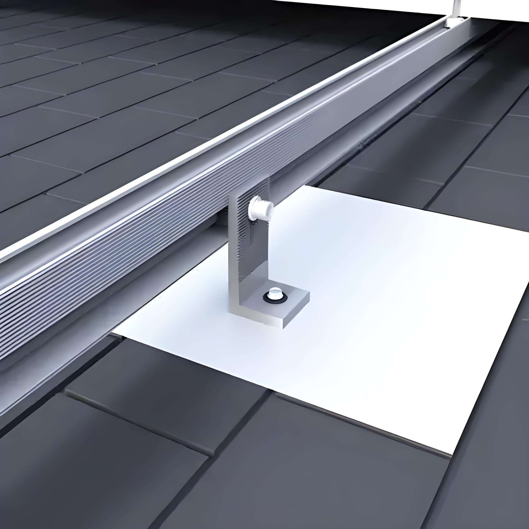
| Exterior platforms, ladders, cable brackets | M10–M16 | A4-70 stainless or HDG 8.8 | External, C5-M |
| Internal service platforms, cable clamps | M8–M12 | 8.8 zinc-plated or A2-70 | Internal, C3 |
The two positions that dominate the engineering conversation are the tower ring flanges and the transition piece to monopile flange. Both are preloaded 10.9-class joints, but they see different corrosion environments and different inspection regimes. The exterior platform and walkway hardware is a different material problem entirely — covered later in Section 4.
2. Tower Ring Flanges: The Main Fatigue Joint
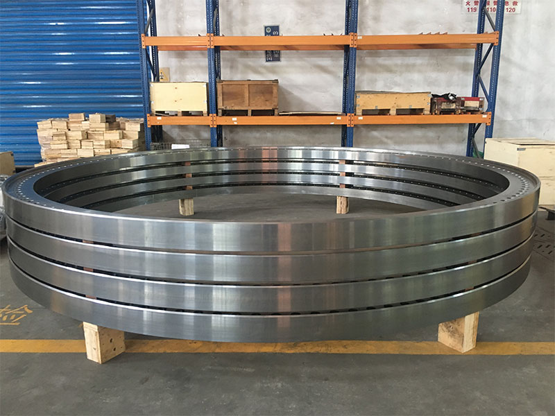
The tower arrives in cylindrical sections 20–30 metres long, each ending in a machined ring flange. The sections are stacked and bolted circumferentially, typically with 80–120 bolts per flange circle on multi-megawatt turbines. These are long, large-diameter bolts — commonly M36 x 320 to M42 x 400 — tensioned hydraulically or by torque-angle.
The design principle: the bolt is preloaded to roughly 70% of yield so the flange faces stay clamped in compression under all operating loads. The alternating wind load then acts on the clamped interface rather than stretching the bolt directly, which keeps the bolt's alternating stress amplitude low. That is what gives the joint its twenty-year fatigue life.
Three controls make that principle work in practice:
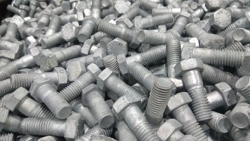
- Post-heat-treatment rolled threads. Rolling the thread form after quenching and tempering produces a continuous grain flow around the thread root and work-hardens the surface, which directionally improves fatigue strength compared with cut threads; the actual benefit depends on thread geometry, preload, surface condition and loading. Cut threads look identical and fail early.
- Friction-controlled coating. The erection torque table is built from a measured friction coefficient on the coated assembly. Zinc flake per ISO 10683 gives a low, stable, documented friction range and is the default on offshore 10.9 tower bolts.
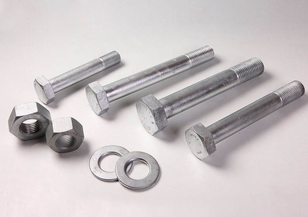
- Matched HV assembly. Bolt, nut and washers come from the same lot under EN 14399-4, with the suitability-for-preloading test run on the assembly. Mixing a bolt from one source with a nut from another invalidates the friction calibration.
We cover the 42CrMo4 material and EN 14399 assembly logic in detail in our 42CrMo4 wind tower bolt specification guide. The point for offshore buyers is that the tower flange bolt is a qualified system, not a commodity bolt.
A note on standards scope. EN 14399-4 HV is a common reference for preloaded structural bolt assemblies in Europe, but tower ring-flange bolting on modern multi-megawatt turbines is frequently governed by the turbine OEM's own bolting system and the project bolt specification rather than by EN 14399-4 alone. OEMs commonly prescribe their own bolt-nut-washer matching, friction class, tensioning procedure and re-torque schedule, and project specs may call up DNV or third-party certification. Where the drawing references an OEM bolting system, that system governs; EN 14399-4 is used as the reference when the drawing does not name a proprietary system. We qualify the assembly to whichever standard the drawing specifies.
3. Transition Piece to Monopile: The Splash-Zone Joint
The transition piece (TP) sits between the monopile foundation and the tower. The flange at the TP-to-monopile connection is the largest bolting on the machine — M48 to M64 — and it sits in the splash zone: alternately wetted by waves, exposed to salt spray, and subject to the most aggressive corrosion environment on the structure.
This joint is different from the tower ring flange in three ways:
- Corrosion environment. The splash zone is worse than the atmospheric C5-M rating. A zinc-flake coating that serves an internal tower flange for twenty years may need a higher-build system at the TP flange, and the bolting is commonly specified hot-dip galvanized per ISO 10684 or zinc-flake over an additional primer, with cathodic protection considered for the substructure.
- Inspection access. The TP flange is above the waterline but at the base of the tower, on an external platform. Inspection means a boat transfer or a crew-transfer trip, which is why the design favours bolting that does not need frequent re-tightening.
- Grout and bolt redundancy. On monopile foundations the TP is often locked to the monopile by a combination of grout and shear bolts / grout joints rather than a full flange, depending on the foundation design. Where a bolted flange is used, it follows the same 10.9 preloaded logic as the tower flange, with the corrosion system upgraded for the splash zone.
For the embedded foundation side of the tower base, we cover the anchor cage and L/J anchor design in the wind turbine foundation anchor bolts guide. The TP flange is the accessible, externally inspected face of that same foundation system.
4. Material Selection: Where 10.9 Ends and Stainless Begins
A common offshore procurement mistake is specifying the same bolt everywhere. The material ladder on an offshore wind farm is chosen by position:
| Position | Material | Why |
|---|---|---|
| Tower ring flanges, TP flange, foundation | 42CrMo4 10.9, zinc flake / HDG | High clamp load, preloaded fatigue joint |
| Exterior platforms, walkways, cable brackets | A4-70 / A4-80 (316L) stainless | C5-M atmosphere, accessible, moderate load |
| Internal cable clamps, ladder rungs | A2-70 or HDG 8.8 | C3 internal environment, cost-optimised |
| Blade-to-hub connections | OEM-proprietary 10.9 system | Supplied by turbine manufacturer |
| Subsea / splash-zone submerged hardware | Duplex 2205 or higher | 316L is marginal for continuous immersion |
The engineering boundary: A4-80 (316L) is not a substitute for a 10.9 structural bolt. Even at 800 MPa tensile, 316L has lower yield than a 10.9 alloy-steel bolt and is not hardened for slip-critical preloaded joints. The tower and TP flanges stay on 42CrMo4 10.9. The 316L belongs on the exterior, corrosion-exposed, accessible hardware where strength is moderate but corrosion life is the controlling factor — platform to bracket bolts, handrail connections, clamp plates.
We cover the 316L / A4-80 selection in detail in our 316L offshore and coastal fasteners guide. For continuous immersion or high-velocity seawater — which the TP flange bolts are not, but submerged mooring or anode hardware is — the specification moves to duplex 2205 or super duplex rather than 316L.
5. Corrosion Protection in C5-M Offshore Service
ISO 12944 classifies the offshore atmospheric environment as C5-M: high salinity, frequent salt spray, dew cycles, and in southern North Sea and Middle East offshore sites, elevated surface temperatures. The coating system on the structural bolting is part of the joint specification:
| Coating | Standard | Typical use on offshore bolting | Notes |
|---|---|---|---|
| Zinc flake (Geomet / Delta-Pro / Dacromet type) | ISO 10683 | Default on 10.9 tower and TP bolts | Low hydrogen risk, stable friction, thin film |
| Hot-dip galvanizing | ISO 10684 | External structural bolts, splash zone | Thicker; threads over-tapped after galvanizing |
| Zinc flake + topcoat / paint system | Per project spec | TP flange and splash-zone positions | Higher build for splash-zone exposure |
| PTFE / Xylan dry film | Per coating spec | Stainless assembly, galling control | Thin film; stabilises K-factor |
Two rules offshore buyers build into the spec. First, electroplated zinc is not used on 10.9 offshore bolts — acid pickling and electroplating introduces hydrogen and risks delayed brittle fracture on high-strength steel. Zinc flake with bake-out, or HDG, is the route. Second, the coating system on the TP splash-zone flange is a project-specific engineering decision, not a catalog choice; the coating spec, thickness and any topcoat should be stated on the inquiry so the quotation returns with the right system.
6. Preload, Friction and Erection Tensioning
Tower and TP flange bolts are preloaded to roughly 70% of yield, set by the turbine designer. Onshore this is commonly done with hydraulic tensioners; offshore it is almost always hydraulic tensioning, because the bolt circle is large and the weather window is short.
Two practical controls:
- Friction coefficient on the assembly. The torque-tension or tensioning procedure is derived from a measured friction test on representative coated assemblies. The target friction value is set by the turbine OEM for the approved coating and bolt system and stated on the drawing, and the erection crew uses the procedure built for that condition; it should not be assumed from a general industry range. Changing the coating without re-calibrating the friction data silently changes the achieved preload.
- Elastic interaction. Tensioning one bolt relaxes its neighbours. A flange circle is therefore tensioned in staged passes in a star pattern, often with a final re-pass around the circle. This is the same staged logic as any large preloaded flange; on an offshore TP flange, the number of passes and the pass schedule are set by the erection procedure.
We cover the preload and friction mechanics in detail in the 42CrMo4 tower bolt guide referenced above. The offshore addition is that the erection procedure is mobilised by boat and weather window, so the bolting has to arrive on site as a qualified, lot-controlled assembly — not mixed-source hardware that the crew has to improvise around.
7. Fatigue Control: Threads, Surface and Inspection
A 10.9 offshore bolt is a fatigue component. Beyond post-heat-treatment thread rolling, the fatigue controls on the bolting pack include:
- Under-head fillet radius — a larger rolled fillet reduces notch sensitivity under the bolt head.
- Surface decarburisation — bar stock is inspected for surface decarburisation, which reduces fatigue strength at the thread root.
- Low-temperature impact — for North Sea and northern Atlantic sites, Charpy impact testing at -20 °C or -40 °C is specified, because 42CrMo4 has a ductile-to-brittle transition that must be verified for the site's minimum design temperature.
- No re-use. Preloaded 10.9 bolts that have been in service are work-hardened; re-tensioning them gives unpredictable preload. Replacement at scheduled maintenance uses new bolts.
These are not optional extras on an offshore order. They are the difference between a bolt that lasts the design life and one that initiates a thread-root crack within two years of commissioning.
8. In-Service Inspection and Re-Tightening
Offshore wind farm maintenance is scheduled around weather windows, so the bolting inspection regime is built into the operating procedure from day one:
- Commissioning — bolt tension verified on the completed flange circle, witness-marked.
- First re-torque / re-tension — typically within the first months after commissioning, to pick up early relaxation.
- Scheduled inspection — periodically (per the turbine OEM's maintenance schedule, often annual or biennial), using calibrated hydraulic tensioners or ultrasonic bolt-length measurement on critical flanges.
- Post-event inspection — after extreme wind or storm events, critical flange tension is re-verified.
The hardware consideration for procurement: witness-mark paint, ultrasonic measurement access on the bolt end, and replacement-bolt availability. A wind farm operator does not want to discover after a storm that the replacement bolts are a different lot with a different friction coefficient. We supply repeat lots of the same assembly specification so scheduled replacement matches the original bolt.
9. Documentation for Offshore Wind QA
An offshore wind bolting order is a qualified-assembly order. The pack wind farm QA / EPC inspectors check:
- EN 10204 3.1 material certificate, per heat, with chemistry and mechanical properties
- Tensile, yield, elongation and hardness test reports (within the 320–380 HV / 33–39 HRC band for 10.9)
- Charpy impact report at the project-specified temperature (-20 °C / -40 °C)
- Friction / preload calibration report for the coated assembly, with the measured friction range
- Coating thickness and adhesion records (zinc flake ISO 10683, or HDG ISO 10684)
- Thread rolling confirmation (rolled after heat treatment, not cut)
- Dimensional inspection: thread gauge fit, head geometry, length, protrusion
- Lot traceability: heat number matching mill certificate to box labels
Third-party witness (SGS, BV, TÜV, DNV) is arranged on critical foundation and TP lots; we hold lots for witness rather than shipping and certifying later.
North American offshore EPC. For projects specified to US standards, the equivalent structural bolting references are ASTM F3125 — the consolidated specification covering high-strength structural bolts (including the former A325, A490 and F1852 grades) — the RCSC Specification for Structural Joints Using High-Strength Bolts, and AISC 360 for the steel structure connection design. Where a North American offshore EPC project calls up these standards in place of EN 14399, we supply the bolting to the equivalent ASTM grade with RCSC-compliant faying surface preparation and documentation; the fatigue, coating and preload controls above apply in either system.
WF Fastener Offshore Bolting — Manufacturing Capability
- Maximum bolt diameter: up to M72 (2-3/4") on tower, transition piece and foundation applications
- Typical offshore structural range: M30–M64 on 10.9 preloaded bolting
- Testing equipment: tensile testing machine up to 1000 kN, Charpy impact pendulum rated to -40 °C, thread gauges (GO / NO-GO), coating thickness and adhesion gauges, friction / torque-preload calibration rig, ultrasonic bolt-length measurement for in-service inspection
- Heat treatment: in-house quench-and-temper furnaces for 42CrMo4 / 1.7228 and related alloy steels
- Annual offshore wind bolting output: on the order of 4,000–6,000 tonnes of structural 10.9 bolting per year across tower, transition piece and anchor positions
10. Supplier Evaluation Card
When comparing offshore wind bolting suppliers, use the points below. They reflect what wind farm procurement and turbine OEM QA teams ask for on qualification audits.
| Evaluation point | What to ask the supplier | Why it matters |
|---|---|---|
| Assembly supply | Can they supply bolt + nut + washers as a matched EN 14399 HV set? | Mixed-source assemblies lose friction calibration |
| Material traceability | Can every bolt be traced to a 42CrMo4 / 1.7228 mill heat? | Untraceable 10.9 bolts fail offshore project audit |
| Thread process | Are threads rolled after heat treatment? | Cut threads reduce fatigue margin on tower joints |
| Friction data | Do they provide measured friction coefficient for the coating? | Without it, the erection tensioning procedure is guesswork |
| Splash-zone coating | Can they supply the upgraded TP flange coating system? | Atmospheric C5-M coating is not enough at the splash zone |
| Low-temp impact | Can they test and report Charpy at -20 / -40 °C? | Northern European sites require verified toughness |
| Hydrogen control | Is zinc flake applied with a bake-out process? | 10.9 bolts are hydrogen-embrittlement-sensitive |
| Repeat lots | Can they reproduce the same lot for O&M replacement? | Scheduled bolt replacement must match the original friction |
| Witness testing | Can they hold a lot for DNV / TÜV / owner witness? | Critical foundation and TP lots are commonly witnessed |
| Certificate format | 3.1 in English, per heat, matching PO line items? | Owner inspectors reject non-conforming cert packs |
11. RFQ Dimensions: What to Send for a Complete Quotation
Offshore bolting inquiries come back with clarifying questions when the assembly standard or friction requirement is missing. Send the following on the first request:
| RFQ field | Example | Notes |
|---|---|---|
| Position | Tower ring flange, TP-to-monopile, or foundation anchor | Changes length, coating and corrosion class |
| Assembly standard | EN 14399-4 HV, or per turbine OEM drawing | State the system, not just "10.9 bolt" |
| Property class | 10.9 per ISO 898-1 | Do not substitute 8.8 or 12.9 without approval |
| Size and length | M42 x 3 x 360 | Pitch and length per drawing |
| Nuts and washers | Included as matched HV set | Required for assembly qualification |
| Coating | Zinc flake ISO 10683, HDG ISO 10684, or TP splash-zone system | State thickness range and friction target |
| Friction coefficient | Per turbine OEM specification | Set by OEM for the approved coating; do not assume a general range |
| Impact requirement | Charpy at -20 °C, 27 J min | For cold-climate sites |
| Exterior hardware | A4-70 / A4-80 316L for platforms | Separate line items from structural bolts |
| Quantity | e.g. 96 sets per flange circle | Bolts and nuts counted as sets |
| Certification | EN 10204 3.1; 3.2 with DNV / TÜV witness if required | Agreed at quotation |
| Delivery timing | Required before installation vessel window | Offshore installation is weather-critical |
Send these fields — or attach the turbine OEM bolting drawing — and we return a complete assembly quotation, with the structural 10.9 sets and the exterior 316L hardware on the same documentation pack.
12. Common Offshore Bolting Mistakes
- Specifying "10.9 bolt" without the assembly standard. A loose 10.9 bolt is not an EN 14399 assembly; the nut, washers and friction behaviour are unqualified.
- Cut threads on fatigue-critical tower bolts. Identical in appearance, lower fatigue margin. Confirm post-heat-treatment rolling.
- Electroplated zinc on 10.9. Hydrogen embrittlement risk. Use zinc flake with bake-out.
- Using the atmospheric C5-M coating on the TP splash-zone flange. The splash zone needs an upgraded system. Specify it separately.
- Changing coating without updating the friction data. The tensioning procedure is built for a measured K; a different coating silently changes preload.
- Substituting 316L for a 10.9 structural bolt. 316L is for exterior accessible hardware, not preloaded flanges.
- Reusing removed tower bolts. Work-hardened 10.9 bolts give unpredictable preload on re-tension. Use new bolts at scheduled replacement.
- No repeat-lot control for O&M. Replacement bolts from a different source have a different friction coefficient. Match the original assembly.
For the high-strength alloy steel side, see the 42CrMo4 wind tower bolt guide; for the exterior 316L side, see the 316L offshore fasteners guide. For the full renewable range, start at the renewable energy fastener center.
FAQ
Q: What bolts are used on offshore wind turbine tower flanges? A: Preloaded property class 10.9 bolts, commonly 42CrMo4 (1.7228) material, supplied as matched EN 14399-4 HV assemblies with nuts and hardened washers from the same lot, typically M36 to M48 on tower ring flanges and M48 to M64 on transition piece and foundation flanges.
Q: What is the difference between tower flange bolts and transition piece bolts? A: Both are 10.9 preloaded joints, but the transition piece to monopile flange sits in the splash zone, where corrosion is more aggressive than the internal tower atmosphere. The TP flange coating is upgraded for splash-zone exposure, and inspection access is external rather than via the internal tower platform.
Q: Is 316L suitable for offshore wind tower flanges? A: No. 316L (A4-80) reaches 800 MPa tensile, below a 10.9 alloy-steel bolt, and is not hardened for preloaded structural joints. Use 316L on exterior platform, walkway and bracket hardware; keep tower and TP flanges on 42CrMo4 10.9.
Q: Why are offshore bolts zinc-flake coated rather than galvanized? A: Zinc flake per ISO 10683 gives a thin, low-hydrogen, stable-friction coating that does not disrupt the calibrated torque-preload relationship. HDG per ISO 10684 is used on some external structural positions but requires over-tapped threads and friction re-calibration. Electroplated zinc is avoided on 10.9 due to hydrogen embrittlement risk.
Q: How often are offshore wind flange bolts re-tightened? A: Per the turbine OEM's maintenance schedule: an early re-tension after commissioning to pick up relaxation, then periodic inspection (often annual or biennial) using calibrated hydraulic tensioners or ultrasonic measurement, and post-storm verification on critical flanges. Replacement bolts are new, not re-used.
Q: What certificates come with an offshore bolting order? A: EN 10204 3.1 per heat, with tensile / yield / hardness, Charpy impact at the specified temperature, friction calibration records, coating thickness and thread-rolling confirmation. 3.2 with DNV / TÜV witness is arranged where the turbine OEM requires it.
Request a Quotation
Send your offshore wind BOM — tower flanges, transition piece, foundation anchors and exterior platform hardware — along with the site corrosivity class and the turbine OEM bolting drawing. We will return line-by-line quotations: 42CrMo4 10.9 HV assemblies for the structural joints, A4-70 / A4-80 316L for the exterior hardware, with coating, friction data and documentation scoped before release.
Email: engineering@wffastener.com
We supply complete offshore wind bolted-connection packages, with the test, friction and certificate scope agreed at quotation so the delivered pack matches the erection procedure and the O&M replacement programme.
Related guides: Renewable Energy Fastener Manufacturing Center, 42CrMo4 10.9 Wind Tower Bolts, 316L A4-80 Offshore & Coastal Fasteners